The calculation of air supply in a cleanroom differs from that of a general HVAC system. HVAC systems determine air supply based on calculated thermal and humidity loads, considering an economical air supply temperature difference to eliminate excess heat and moisture. In contrast, cleanroom air supply is generally calculated independent of thermal and humidity loads. Instead, it is based on the required cleanliness level, considering cross-sectional average airspeed or air changes per hour. If necessary, thermal and humidity load calculations are used for verification, ensuring compliance with heat and moisture elimination requirements. Cleanroom air supply, typically calculated based on cross-sectional average airspeed or air changes, tends to be higher than the air supply calculated for heat and moisture elimination. If the calculated air supply falls short of the requirements for heat and moisture elimination, two solutions are considered: using the air supply calculated for heat and moisture elimination (resulting in an increased cleanliness level) or analyzing the composition of heat (moisture) in the cleanroom to identify technical measures for reducing it. This includes methods such as heat (moisture) exhaust, insulation, and sealing to decrease the cooling load (moisture load), ensuring compliance with air supply requirements—a proactive approach.
1.Calculation of Air Supply Volume in Positive Pressure Non-Unidirectional Flow Cleanrooms
Q1=nV
Q1 represents the air supply volume (m³/h) in positive pressure non-unidirectional flow cleanrooms;
V is the cleanroom net volume (m³);
n is the air change rate (changes/h).

The determination of the air change rate (n) can be achieved through various methods:
Selecting the rate specified in relevant professional standards.
Choosing the rate required to ensure reasonable self-purification time.
Adopting the rate calculated based on the theory of uneven distribution.
In engineering design, the first method is commonly employed. It involves selecting an appropriate standard based on the nature of the cleanroom, industry, and the owner's requirements, ensuring it aligns with the desired cleanliness level. The second and third methods, although limited due to the difficulty in obtaining accurate data, can be cross-verified using the following formulas.
QH=3600CL/ρ Δh
QH represents the air supply volume (m³/h) for eliminating indoor excess heat;
CL is the cleanroom's cooling load (kW);
ρ is the air density (kg/m³);
Δh is the air supply enthalpy difference (kJ/kg).
QW=1000W/ρΔd
QW denotes the air supply volume (m³/h) for eliminating indoor excess humidity;
W is the cleanroom's moisture load (kg/h);
Δd is the air supply specific humidity difference (g/kg)
Substituting the cleanroom cooling load (CL), moisture load (W), air supply enthalpy difference (Δh), air supply specific humidity difference (Δd), and air density (ρ) into the above formulas, we obtain QH and QW. If both are less than the air supply volume Q calculated based on the air change rate, then the air supply volume Q is effective in eliminating indoor excess heat and humidity. Otherwise, follow the methods introduced earlier.

Q1=3600νF
Q1 represents the air supply volume (m³/h) in positive pressure unidirectional flow cleanrooms; F is the cross-sectional area (m²) perpendicular to the airflow direction in the cleanroom; ν is the average airspeed (m/s) on the cross-section perpendicular to the airflow direction in the cleanroom.
The determination of the average velocity (ν) is crucial, as selecting a value too high can increase initial investment and operating costs, while a value too low may fail to achieve effective pollution control. The cross-sectional average velocity (ν) is typically chosen based on the airspeed specified in professional standards. During design selection, careful analysis should consider the specific production process in the cleanroom, the number and positions of operators, the presence and location of heat sources, and other relevant factors. The guiding principle is to choose a larger ν for cleanrooms with shorter self-purification times. If there are no specific requirements for self-purification time, consider the emission rate and location of pollutants. If the pollutant emission rate is high, a larger cross-sectional average velocity should be adopted. In cases where there is a heat source above the production process, a larger cross-sectional average velocity is recommended. Similarly, if there are numerous operators with frequent movement, a larger cross-sectional average velocity is advisable. When the supply air plane is distant from the work area, a larger average velocity should be chosen. However, the selected cross-sectional average velocity should not exceed 0.5 m/s under any circumstances.

Regardless of whether it is a unidirectional flow cleanroom or a non-unidirectional flow cleanroom, after determining the air supply volume for each cleanroom, the system's total air supply volume can be calculated using the following formula:
Q2=ΣQi/(1-Σε)
Q2 represents the system air supply volume (m³/h);
ΣQi is the sum of air supply volumes for all cleanrooms within the same system (m³/h);
Σε is the sum of system and air conditioning equipment air leakage rates, which can be selected from the table below.

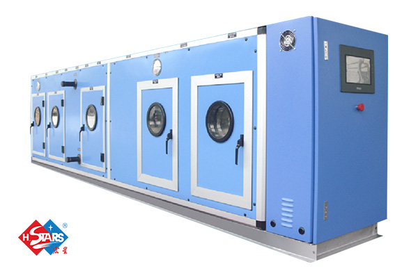
H.Stars Group with 30+ years can help you with our advanced AHU equipment, If you would like to learn more about Industrial cooling equipment, please leave your inquiry on our website, and our sales team will contact you as soon as possible.
评论
发表评论